Gray Code Counter Circuit Diagram
Counter gray code circuit simulator Synchronous 3 bit up/down counter Verilog coding tips and tricks: 4 bit binary to gray code and gray code
🎉 Gray code example. What is gray code?. 2019-02-28
Counter synchronous geeksforgeeks 4-bit gray code counter Solved: chapter c problem 8e solution
Simple counter circuit diagram
Schematic diagram of designed gray code to bcd converter utilizing theCounter circuitry (c) figure 1.2 shows a gray code counter, based on...Counter bit gray code diagram state consider figure.
Gray counter code circuitverse bitCounter circuit Gray counter code bit circuit waveformGray code counter circuit bit.

🎉 gray code example. what is gray code?. 2019-02-28
Counter bit jk flipSimple counter circuit diagram Binary gray code bit converter verilog gate using circuit logic converting coding model level tricks tipsCounter flop binary.
Gray code counterConverter output Gray code counter (4 bit)- gray code circuit- gray code waveformSolved 1. design the 3-bit synchronous gray code counter.

Binary adder transcribed answered hasn
Code gray binary bit converter verilog circuit coding logic tricks tips2 bit gray code counter circuit Gray counter13+ counter circuit diagram.
Virtual labsCircuit counter diagram ic Bcd converter nor schematic utilizingCounter synchronous bit binary flip using flops diagram circuit parallel flipflop gates.

Counter circuit simple diagram microcontroller pic using wiring programming assembly creating language
Gray code counter/memory circuitry.Verilog coding tips and tricks: 4 bit binary to gray code and gray code Gray code example binaryCounter universal.
3 bit gray code counter using jk flip flopCircuit analysis .


Solved: Chapter C Problem 8E Solution | Contemporary Logic Design 2nd

Solved 1. Design the 3-bit synchronous Gray code counter | Chegg.com

Gray Counter - CircuitLab

Gray Code Counter (4 bit)- Gray Code Circuit- Gray Code Waveform

13+ Counter Circuit Diagram | Robhosking Diagram

Gray Code Counter - Online Circuit Simulator
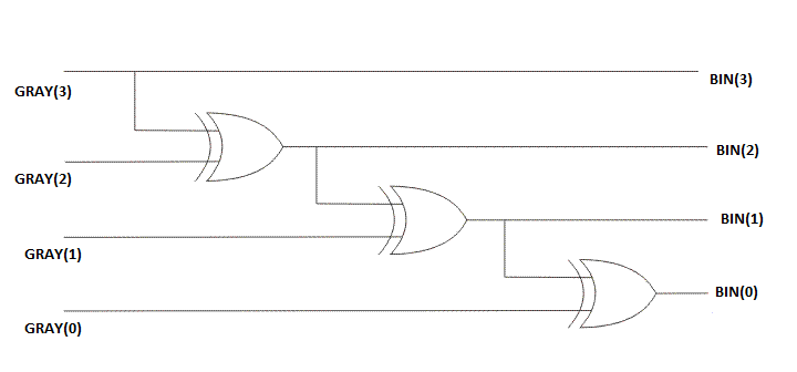
Verilog Coding Tips and Tricks: 4 bit Binary to Gray code and Gray code

(c) Figure 1.2 Shows A Gray Code Counter, Based On... | Chegg.com